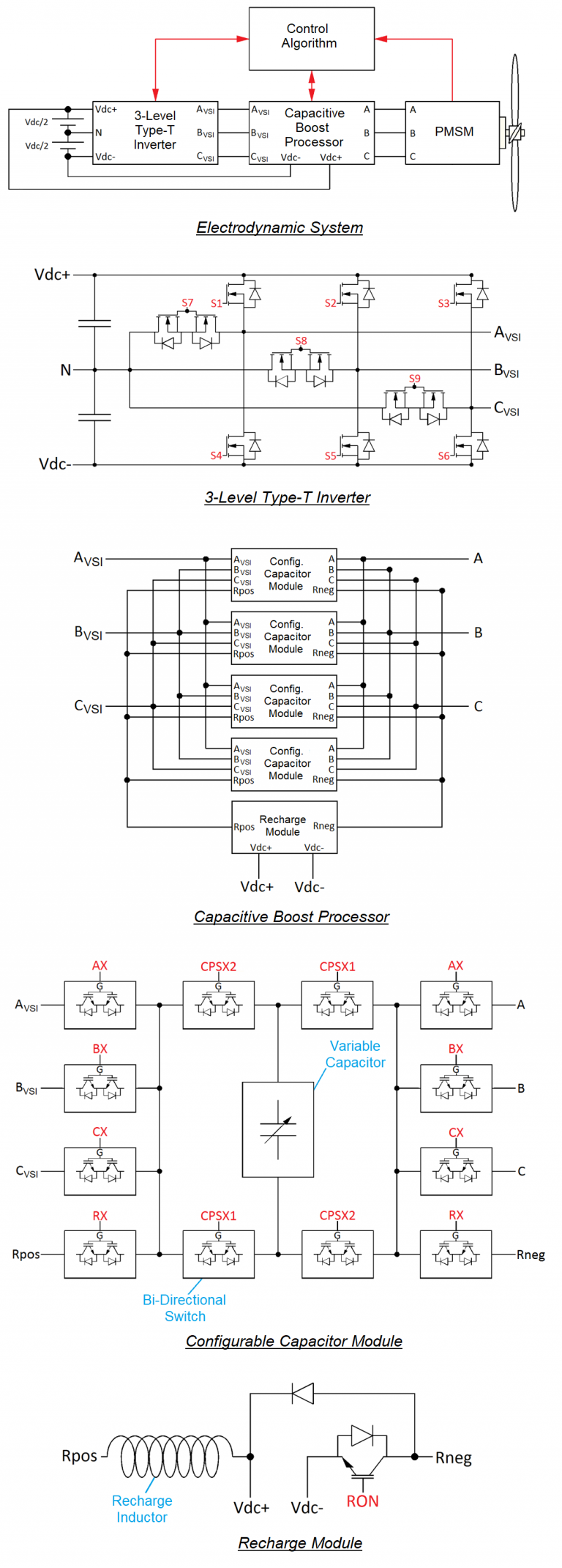
Concept
The technology, called Capacitive Boost Processor, offers a solution that uses the properties of electrical resonance to power a permanent magnet synchronous motor. The concept of the technology is to connect a pre-charged capacitor in series with each phase of the motor at all times during its high-speed operation, i.e. when the battery voltage is no longer sufficient to reach the maximum torque. The sum of the inverter voltage and the pre-charged capacitor significantly increases the available phase voltage and allows maximum torque to be achieved over a wide speed range.
The architecture of the Capacitive Boost Processor is modular. To adapt to a three-phase motor, it contains four Configurable Capacitor Modules (CCMs) and a Recharge Module. Alternately, each CCM connects to a motor phase to discharge or to the Recharge Module to recharge. At any given time, three Configurable Capacitor Modules (CCMs) discharge in a motor phase while the last CCM recharges through the Recharge Module. Each CCM can determine its polarity relative to the motor phase or the Recharge Module thanks to the H-bridge.
The capacitive-inductive circuit created by the CCM and the Recharge Module benefits from resonant dynamics to recover residual capacitive energy and thus raise the capacitor voltage above the battery voltage.
The three-level T-type inverter assists the capacitor discharge to shape a smooth sinusoidal phase current aligned with the back EMF vector to generate the maximum torque per amp.
Phase current, rotor angular position and capacitor voltage sensors allow the control algorithm to obtain the information necessary for motor operation. The control algorithm manages the operation of the inverter and the Capacitive Boost Processor in order to operate the motor at the desired torque and speed. Among other things, the control algorithm determines the polarity of each CCM, assigns the CCMs to the motor phases or to the Recharge Module, controls the inverter output voltage and manages the recharging of the capacitors in order to obtain the desired capacitive energy level before the discharge cycle begins.
Bi-directional switches are implemented by connecting two transistors in antiparallel (face to face). In this way, bi-directional switches allow either free current flow in both directions or complete current cutoff in both directions. Since the dynamics of discharge and recharge are a function of capacitances and inductances, the passive electronic components are sized so that the recharging and discharging dynamics correspond to the operating needs of the system, in symbiosis with the electric motor.
